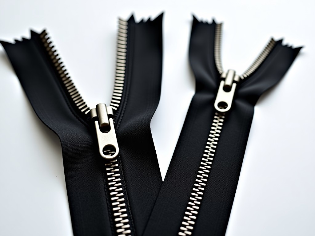
Metal Zipper Machinery for Wholesale Production
Overview
Metal zipper machinery performs the sequential steps of coil feeding, tooth forming, tape welding, and final cutting to produce continuous metal zipper chains.
The process relies on precision rollers and dies that maintain tolerances within ±0.02 mm to ensure consistent tooth pitch.
Automation levels range from semi‑automatic feed systems to fully servo‑driven lines capable of 120 m/min output.
Typical machine widths accommodate zipper tapes from 3 mm to 10 mm, with adjustable guide rails to handle different coil thicknesses.
Changeover between sizes is facilitated by quick‑release tooling plates that can be swapped in under 8 minutes.
Power consumption depends on drive configuration; a typical 3‑kW servo motor drives the forming station while auxiliary motors account for approximately 0.8 kW for tape tension.
Energy usage is monitored via an integrated PLC that logs kWh per shift, enabling operators to optimize cycle times.
Cooling is achieved through a closed‑loop water jacket that maintains die temperature within 20 °C ± 2 °C to prevent thermal expansion.
Lubrication points are serviced by a centralized grease pump delivering NLGI‑2 grade grease at 0.15 ml per cycle.
Safety interlocks conform to ISO 13849‑1 PL e standards, halting motion if guard doors are opened.
Technical Specifications
Technical data presented below reflects standard configurations; actual values can be adjusted according to project requirements.
All dimensions are given in millimeters unless otherwise noted.
| Parameter | Typical Value | Adjustable Range | Notes |
|---|---|---|---|
| Machine Width (tape) | 6 mm | 3 mm – 10 mm | Guide rails interchangeable |
| Tooth Pitch | 4.0 mm | 3.0 mm – 5.0 mm | Die set dependent |
| Production Speed | 100 m/min | 60 – 150 m/min | Servo drive optional |
| Motor Power (main) | 3 kW | 2 – 5 kW | AC servo |
| Voltage | 380 V 3‑phase | 220 V – 440 V | Transformer available |
| Control System | PLC + HMI | Programmable logic | Optional SCADA |
| Machine Weight | 1 200 kg | 1 000 – 1 500 kg | Includes base frame |
Routine maintenance involves checking die wear every 500 hours of operation and replacing worn rollers when surface roughness exceeds 1.6 µm Ra.
Spare parts kits are available for rapid exchange, reducing mean time to repair below 30 minutes.
Application Areas
Metal zippers are prevalent in outerwear, luggage, and industrial protective gear where durability against abrasion and corrosion is required.
The forming machine’s ability to produce brass, aluminum, and zinc‑alloy teeth allows manufacturers to match zipper material to the specific environmental exposure of the end product.
High‑speed continuous operation reduces labor costs in large‑scale garment factories that demand consistent tooth geometry across thousands of meters of tape.
- Outerwear jackets – need corrosion‑resistant brass teeth for marine environments.
- Luggage and bags – benefit from aluminum teeth for lightweight strength.
- Heavy‑duty workwear – require reinforced zinc‑alloy teeth for abrasion resistance.
- Automotive interior trim – use coated steel teeth for UV stability.
- Sports equipment – select stainless‑steel teeth for sweat resistance.
Customization Options
Customization begins with selecting tooth profile geometry, which influences both flexibility and lock strength.
Clients can specify die sets for standard coil, reverse coil, or waterproof sealed zippers, each requiring distinct forming angles.
Adjustable guide rails and interchangeable spacers enable the machine to handle tape widths from 2 mm to 12 mm without mechanical redesign.
- Tooth profile – standard, reverse, waterproof, concealed.
- Tape width – 2 mm to 12 mm in 0.5 mm increments.
- Material – brass, aluminum, zinc‑alloy, stainless steel.
- Drive type – servo, stepper, hybrid.
- Control interface – PLC, HMI, remote IO.
Quality Control & Testing
We implement statistical process control on critical dimensions such as tooth height and pitch variance.
Each production lot undergoes sampling where 10 mm sections are measured with a laser micrometer, targeting a tolerance of ±0.015 mm.
Functional testing includes zipper pull‑force measurements, aiming for a minimum of 25 N for brass teeth and 18 N for aluminum.
Visual inspection is performed under 10× magnification to detect surface defects such as burrs or misaligned teeth.
Frequently Asked Questions
Can the machine be customized for non‑standard tooth pitches?
Yes, tooth pitch can be adjusted by changing the forming die set; typical ranges from 3.0 mm to 5.0 mm are available, and custom pitches are quoted upon receipt of detailed drawings.
What information is required before quotation?
Please provide tape width, material choice, desired output speed, and any special features such as waterproof sealing or reverse coil configuration.
How is quality inspected?
Quality is verified using laser micrometry for dimensional accuracy and pull‑force testing for tooth strength, as outlined in the Quality Control section.
What packaging methods are available for export shipments?
Machines are secured on steel pallets, wrapped in shrink film, and placed in wooden crates with foam corner protection; optional container loading assistance is offered upon request.
What is the typical production lead time?
Standard models ship within 4–6 weeks after receipt of deposit, while fully customized units may require 8–10 weeks depending on complexity.
Contact for Inquiry
For detailed technical discussions or to request a quotation, please contact our engineering team.
We respond to inquiries within one business day and can arrange virtual machine walkthroughs upon request.
Contact Us