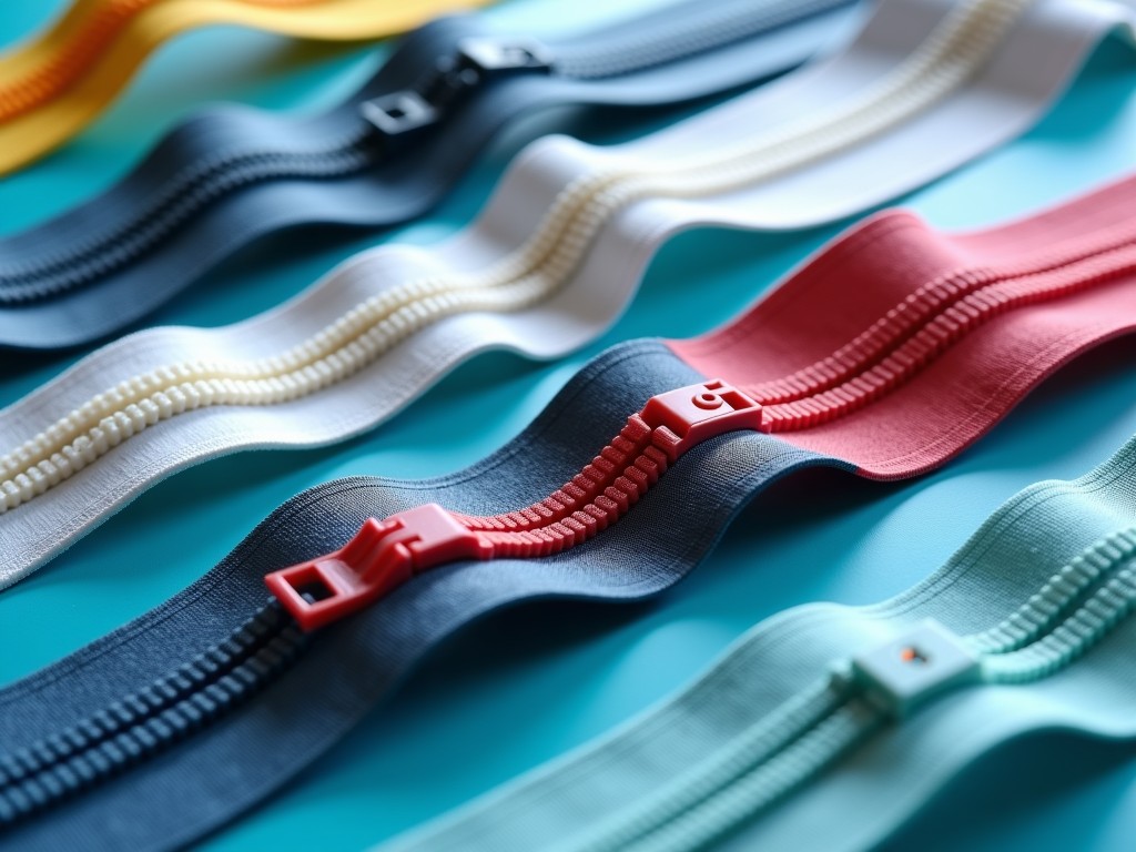
Wholesale Plastic Zipper Production Line
A plastic zipper production line integrates extrusion, molding, and assembly equipment to manufacture continuous zipper tapes and sliders at high volume. The line is engineered for consistent tooth geometry, precise tape width, and reliable slider attachment, enabling wholesale suppliers to meet OEM specifications for apparel, luggage, and industrial goods.
Key Technical Features
The extrusion system uses a co‑rotating twin‑screw design with L/D ratio of 28:1, allowing precise melt temperature control within ±2 °C for uniform polymer flow. Die geometry is adjustable to produce tape widths from 3 mm to 25 mm with tolerance ±0.05 mm. Tooth forming modules employ interchangeable steel molds that achieve tooth pitch accuracy of 0.2 mm and height variation under 0.03 mm.
- Modular drive stations rated 5–15 kW, configurable for different output rates
- Integrated cooling chillers maintaining tape temperature below 40 °C before winding
- Automatic slider insertion heads with placement accuracy ±0.1 mm
- Closed‑loop tension control keeping tape tension variation under 0.5 N
- Touch‑screen HMI with recipe storage for over 50 product variants
Typical Specifications
| Parameter | Typical Value | Notes |
|---|---|---|
| Maximum Line Speed | 120 m/min | Dependent on tape width and tooth pitch |
| Installed Power | 22 kW | Includes extrusion, drives, and auxiliaries |
| Tape Width Range | 3–25 mm | Adjustable die set |
| Tooth Pitch Options | 2.5 mm, 3.0 mm, 4.0 mm | Custom molds available |
| Slider Compatibility | Metal, plastic, injection‑molded | Quick‑change tooling |
| Control System | PLC with Ethernet/IP | Recipe‑based operation |
Production Process Overview
Raw resin pellets are first dried in a hopper dryer to moisture content below 0.02 % to prevent hydrolysis during extrusion. The dried melt enters the twin‑screw extruder where temperature zones are set according to polymer grade, typically 180–210 °C for polyacetal. After extrusion, the tape passes through a calibration die that sets width and thickness before entering the tooth forming station.
Tooth forming stations use precision molds that interlock with the tape surface, creating uniform teeth on both sides. The formed tape then moves to a cooling belt where forced air reduces temperature to below 40 °C, stabilizing dimensions. Subsequently, the tape is wound onto a spool under controlled tension, preparing it for slider insertion.
Slider insertion heads place pre‑formed sliders onto the tape at a programmed pitch, using pneumatic actuators to crimp the slider onto the teeth. An inline vision system inspects each slider for correct orientation and tooth engagement, rejecting any units that fall outside set tolerances. Accepted product proceeds to a final inspection station where tensile strength and tape width are measured before packaging.
Customization Options
Customers can specify screw diameter ranging from 45 mm to 90 mm to match desired throughput and material viscosity. Die inserts can be swapped to produce specialty profiles such as water‑repellent coated tapes or flame‑retardant grades. Mold cavities are available in configurations from 2 to 8 teeth per cycle, allowing adjustment of tooth density for different applications.
Control system upgrades include optional MES integration for real‑time production data logging and remote diagnostics. Additional accessories such as anti‑static bars, edge trimming units, and inline printing stations can be added to meet specific end‑use requirements. All modifications are engineered to maintain line balance and avoid resonance issues.
Quality Control Philosophy
Quality assurance relies on three layers: in‑process monitoring, periodic sampling, and final product validation. Inline laser gauges continuously measure tape width and thickness, triggering automatic adjustments if deviation exceeds 0.03 mm. Every hour, a sample tape is subjected to tensile testing according to ASTM D2256, with results recorded for batch traceability.
Slider attachment strength is evaluated using a peel test rig that measures the force required to separate slider from teeth, ensuring a minimum of 12 N per tooth for standard grades. Visual inspection stations employ high‑resolution cameras with 0.01 mm resolution to detect missing teeth, flash, or misaligned sliders. All data are stored in the line’s historian for analysis and continuous improvement.
Applications and Industry Fit
In apparel manufacturing, consistent tooth pitch and low friction tape enable smooth operation of high‑speed sewing machines, reducing needle wear and seam defects. The ability to produce narrow tapes (3–5 mm) supports lightweight garments where bulk must be minimized while maintaining closure strength.
For luggage and outdoor gear, the line can produce wide tapes (20–25 mm) with reinforced tooth profiles that withstand repeated loading cycles exceeding 5,000 pulls without deformation. UV‑stabilized resin options further extend service life in sunlight‑exposed environments.
Industrial sectors such as automotive interior trims and medical device pouches benefit from the line’s capability to process specialty polymers like POM‑CO or TPU blends, providing chemical resistance and sterilization compatibility. Precise width control ensures proper integration with ultrasonic welding or adhesive bonding processes.
Frequently Asked Questions
Can the line be configured for different tooth pitches?
Yes, tooth pitch is determined by the interchangeable molding inserts. Standard pitches of 2.5 mm, 3.0 mm, and 4.0 mm are available, and custom pitches can be quoted based on specific tooling lead times.
What information is needed for a quotation?
To prepare a detailed quote we require the target tape width, tooth pitch, slider type, expected output rate (meters per minute), and any special material requirements such as additives or certifications.
How is quality inspected during production?
Inline laser gauges monitor tape dimensions, a vision system checks slider placement and orientation, and periodic tensile and peel tests verify mechanical properties. All inspection points are logged with timestamps for traceability.
What are the typical lead times for delivery?
Standard configurations ship within 10–12 weeks after receipt of purchase order. Custom tooling or extensive mechanical modifications may extend lead time to 16–18 weeks.
Get in Touch
For technical discussions, feasibility studies, or to request a formal quotation, please contact our engineering team.
Request a Quote